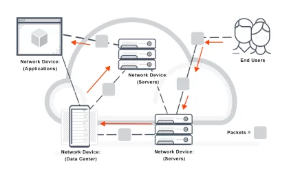
An overall telecommunications network (i.e., the PSTN) consists of local networks interconnected by one or more long-distance networks. The concept is illustrated in Figure 1.1. This is the PSTN, which is open to public correspondence. It is usually regulated by a government authority or may be a government monopoly, although there is a notable trend toward privatization. In the United States the PSTN has been a commercial enterprise since its inception.
End-Users, Nodes, and Connectivity’s
End-users, as the term tells us, provide the inputs to the network and are recipients of network outputs. The end-user employs what is called an I/O, standing for input/output

(device). An I/O may be a PC, computer, telephone instrument, cellular/PCS telephone or combined device, facsimile, or conference TV equipment. It may also be some type of machine that provides a stimulus to a coder or receives stimulus from a decoder in say some sort of SCADA2 system.
End-users usually connect to nodes. We will call a node a point or junction in a transmission system where lines and trunks meet. A node usually carries out a switching function. In the case of the local area network (LAN), we are stretching the definition. In this case, a network interface unit is used, through which one or more end-users may be connected.
A connectivity links an end-user to a node, and from there possibly through other nodes to some final end-user destination with which the initiating end-user wants to communicate. Figure 1.2 illustrates this concept. The IEEE (Ref. 2) defines a connection as “an association of channels, switching systems, and other functional units set up to provide means for a transfer of information

between two or more points in a telecommunications network.” There would seem to be two interpretations of this definition. First, the equipment, both switching and transmission facilities, are available to set up a path from, say, Point A to Point B. Assume A and B to be user end-points. The second interpretation would be that not only are the circuits available, but also they are connected and ready to pass information or are in the information passing mode.
At this juncture, the end-users are assumed to be telephone users, and the path that is set up is a speech path (it could, of course, be a data or video path). There are three sequential stages to a telephone call.
1. Call setup
2. Information exchange
3. Call takedown
Call setup is the stage where a circuit is established and activated. The setup is facilitated by signaling, 3 which is discussed in Chapter 7. It is initiated by the calling subscriber (user) going off-hook. This is a term that derives from the telephony of the early 1900s. It means “the action of taking the telephone instrument out of its cradle.” Two little knobs in the cradle pop up, pushed by a spring action causing an electrical closure. If we turn a light on, we have an electrical closure allowing electrical current to pass. The same thing happens with our telephone set; it now passes current. The current source is a “battery” that resides at the local serving switch. It is connected by the subscriber loop. This is just a pair of copper wires connecting the battery and switch out to the subscriber premises and then to the subscriber instrument. The action of current flow alerts the serving exchange that subscriber requests service. When the current starts to flow, the exchange returns a dial tone, which is audible in the headset (of the subscriber instrument). The calling subscriber (user) now knows that she/he may start dialing digits or pushing buttons on the subscriber instrument. Each button is associated with a digit. There are 10 digits, 0 through 9. Figure 1.3 shows a telephone end instrument connected through a subscriber loop to a local serving exchange. It also shows that all-important battery (battery feed bridge), which provides a source of current for the subscriber loop.
If the called subscriber and the calling subscriber are in the same local area, only seven digits need be dialed. These seven digits represent the telephone number of the called subscriber (user). This type of signaling, the dialing of the digits, is called address signaling. The digits actuate control circuits in the local switch, allowing a connectivity to be set up. If the calling and called subscribers reside in the serving area of that local switch, no further action need be taken. A connection is made to the called subscriber line, and the switch sends a special ringing signal down that loop to the called subscriber.


and her/his telephone rings, telling her/him that someone wishes to talk to her/him on the telephone. This audible ringing is called alerting, another form of signaling. Once the called subscriber goes off-hook (i.e., takes the telephone out of its cradle), there is activated connectivity, and the call enters the information-passing phase or phase 2 of the telephone call.
When the call is completed, the telephones at each end are returned to their cradle, breaking the circuit of each subscriber loop. This, of course, is analogous to turning off a light; the current stops flowing. Phase 3 of the telephone call begins. It terminates the call, and the connecting circuit in the switch is taken down and is then freed-up for another user. Both subscriber loops are now idle. If a third user tries to call either subscriber during stages 2 and 3, she/he is returned a busy-back by the exchange (serving switch). This is the familiar “busy signal,” a tone with a particular cadence. The return of the busy-back is a form of signaling called call-progress signaling.
Suppose now that a subscriber wishes to call another telephone subscriber outside the local serving area of her/his switch. The call setup will be similar as before, except that at the calling subscriber serving switch the call will be connected to an outgoing trunk. As shown in Figure 1.4, trunks are transmission pathways that interconnect switches. We repeat: Subscriber loops connect end-users (subscriber) to a local serving switch; trunks interconnect exchanges or switches.
The IEEE (Ref. 2) defines a trunk as “a transmission path between exchanges or central offices.” The word transmission in the IEEE definition refers to one (or several) transmission media. The medium might be wire-pair cable, fiber-optic cable, microwave radio, and, stretching the imagination, satellite communications. In the conventional telephone plant, coaxial cable has fallen out of favor as a transmission medium for this application. Of course, in the long-distance plant, satellite communication is fairly widely employed, particularly for international service. Our reference above was for local service.


Comments are closed.