The equalizer is a device that attempts to reverse the distortion incurred by a signal transmitted through a channel. In digital communication its purpose is to reduce inter symbol interference to allow recovery of the transmit symbols. It can be a simple linear filter or a complex algorithm. The types of commonly used equalizers in digital communications are:
§ Linear Equalizer: It processes the incoming signal with a linear filter.
§ MSME equalizer: It designs the filter to minimize E[|e|2], where e is the error signal that is the filter output minus the transmitted signal.
§ Zero forcing Equalizer: It approximates the inverse of the channel with a linear filter.
§ Decision feedback equalizer: It augments a linear equalizer by adding a filtered version of previous symbol estimates to the original filter output filter.
§ Blind Equalizer: It estimates that the transmitted signal without knowledge of the channel statistics and uses only knowledge of the transmitted signal’s statistics.
§ Adaptive Equalizer: It is typically a linear equalizer or a DFE, which updates the equalizer parameters (such as the filter coefficients) as it is processes the data. It uses the MSE cost function and it assumes that it makes the correct symbol decisions and uses its estimate of the symbols to compute e which is defined above.
§ Viterbi Equalizer: It Finds the optimal solution to the equalization problem. It is having a goal to minimize the probability of making an error over the entire sequence.
§ BCJR Equalizer: It uses the BCJR algorithm whose goal is to minimize the probability that a given bit was incorrectly estimated.
§ Turbo Equalizer: It applies turbo decoding while treating the channel as a convolutional code.
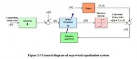
A more efficient and direct approach is to search for the best possible equalizer weight vector adaptively, without identifying the channel in advance. The equalization algorithms for unknown channels are divided into the supervised mode in which a training or pilot sequence known by the receiver is transmitted. Training period apparently takes part of the available air time and bandwidth, and it might be very inefficient or even unfeasible in multi-user environments. In spite of wasting resources, supervised techniques are simple and have guaranteed success in convergence. Qureshi (1982, 1985) has provided excellent references and tutorials on supervised adaptive equalization. The general concept of supervised algorithms is depicted in Figure 2-3, in which a linear (transversal) equalizer filter is adaptively trained for best possible weight or state vector.
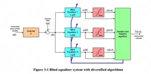
In blind equalization techniques, the channel equalization or estimation is based solely on the received signal samples. It is also assumed that statistical properties of the input data to the channel are known and incorporated in the corresponding computations.Blind techniques in wireless channel equalization are diversified and abundant; nonetheless, a robust and fast convergent technique with reasonably efficient computations remains as an open problem. In particular Fractionally-Spaced Equalization (FSE) and the algorithms using Higher Order Statistics (HOS) were not visited. The reason of such negligence is the fact that various techniques of FSE and HOS are computationally costly and our target systems with multiple algorithms need to employ relatively simple methods to keep overall computational cost of the system affordable.
For a fractionally spaced equalizer (FSE), the tap spacing of the equalizer is a fraction of the baud spacing (in time) or the transmitted symbol period. As the output of the equalizer has the same rate as the input symbol rate and the output of the FSE needs to be calculated once in every symbol period of transfer. At this situation the FSE can be modeled as the parallel combination of a number of baud spaced equalizers in communication. This type of parallel combination of baud spaced equalizers is called as the Multi-Channel Model of FSE. The Multi-Channel Model of FSE for an oversampling factor of two was derived in one of the earlier works . The over-sampling factor describes the tap spacing of the FSE. If T is the symbol period, then oversampling factorT tapspacing = (2.1).
Comments are closed.