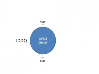
CMOS Digital Logic Circuits
The Logic family is composed of different types of digital logic circuits:
· RTL
· DTL
· TTL
· CMOS

Ø Logic AND can be implemented by a series combination of two MOS transistors, which conducts electricity if both are turned on and conducting.
Ø Logic OR can be implemented by a parallel combination of two MOS transistors, which conduct electricity if either of them is turned on and conducting.
Due to such logic properties of the series and parallel connections of the MOS transistors, various logic circuits can be constructed to realize any arbitrary logic function by two complementary networks of MOS transistors:
Ø The pull-up network composed of pMOS transistors connected to the positive voltage source ![]() so that the circuit will conduct.
so that the circuit will conduct.
Ø The pull-down network composed of nMOS transistors connected to ground, so that the circuit will conduct.
These two pull-up and pull-down networks will turn on and off alternatively, depending on the input variables of the logic function, so that the output voltage is high for logic 1 
![]() , but low for logic 0 if
, but low for logic 0 if 
![]() .
.

Negation
The NOT gate is implemented by a pull-up circuit composed of only a pMOS transistor and its complementary pull-down circuit composed of only a nMOS transistor:


| (180) |
More complicated logic functions can be similarly implemented using CMOS circuits.